-
Your shopping cart is empty!
MENU
Your shopping cart is empty!
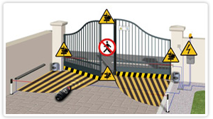
Anyone installing automatic gates in the UK needs to know what the safety risks are, and where to find the right information on gate safety.
So, we've put together the article you'll find at the bottom of this page to answer all the questions about safe gate installation that we are commonly asked.
Talk To An Expert
Do you need help selecting the right product for the job?
Call our local rate number now for product and technical support.


Use our reference guide to show which Faac motors this release key is compatible with.All Faac manua..
£5.67 Ex VAT £6.80 Inc VAT

00058P2029 lever release lockPack of two Faac 770N underground motor. ..
£25.80 Ex VAT £30.96 Inc VAT


We are sorry but this product is no longer available. We have listed suitable alternatives below und..
£11.33 Ex VAT £13.60 Inc VAT

EVA.LAMPBeninca EVA.LAMP Circuit & flashing light for EVA.5/EVA.7 road barrier ..
£27.30 Ex VAT £32.76 Inc VAT

We are sorry but this product is no longer available. We have listed suitable alternatives below und..
£4.03 Ex VAT £4.84 Inc VAT

Rubber profile for self-assembly safety edgesClip foot Available in 45mm or 65mm high versions Pr..
£39.62 Ex VAT £47.54 Inc VAT

Endcaps for different sizes of safety profiles with self-seal.End caps with an 8.2kOhm resistor for ..
£21.72 Ex VAT £26.06 Inc VAT

ASO Aluminium Profile For Different Rubber Profile Depth.Suitable for 45mm or 65mm rubber profile ..
£11.29 Ex VAT £13.55 Inc VAT

ASO endcap for 45mm profile with 2.5m cable ..
£28.92 Ex VAT £34.70 Inc VAT

ASO self-seal endcap for 65mm profile with 0.5m cable ..
£21.19 Ex VAT £25.43 Inc VAT

Tool for cutting 45mm and 65mm safety edge rubber profiles. ..
£101.08 Ex VAT £121.30 Inc VAT

Compact design Energy efficient Easy to install and setup Reliable Cost effective Th..
£117.94 Ex VAT £141.53 Inc VAT

Indicator lights for click fixture of X-BAR on upper or lower side of pole. ..
£64.77 Ex VAT £77.72 Inc VAT
Because this is such an important subject, we’ve put this article together. It highlights the important issues and covers the best practices a good gate installer should always use.
While the UK gate automation industry isn’t regulated, there are a number of guidelines that all UK automatic gate engineers should know and apply.
Automatic gates are made up of different components. These include the gate or gates, the automation system components, safety devices, locks hardware such as hinges, tracks, racks and stops, plus access control devices. The assembly of these components into automatic gates creates a new 'machine'. The Machinery Directive says that a new machine must be CE marked by the installer that created it.
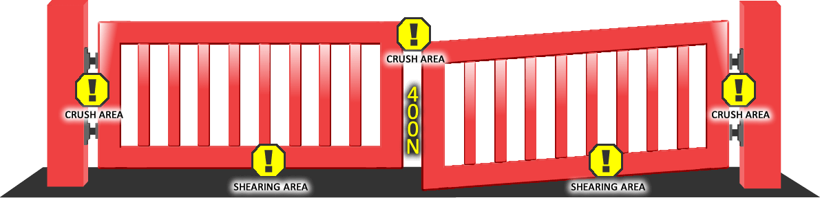
In order to open or close, swing and sliding gates move. This is when they can hit something or someone or cause injury in conjunction with fixed objects such as railings or gate posts. These impacts can cause injuries classified as impact, crushing, drawing in, hooking, cutting or shearing.
Badly installed swing gates would be more likely to cause impact and crushing injuries while dangerous sliding gates are responsible for more impact, crushing and shearing injuries.
Two important physical factors affecting levels of risk are the weight of the gate(s) and the speed that they move. When moving, heavier gates carry more momentum and transmit greater force to anything they hit. Similarly, gates moving faster carry more momentum than slower gates.
Gate automation motor choice plays a role in how much force is needed to move automated gates. As an automated swing gate system works like a lever and fulcrum, pushing and pulling the gate open and closed as far from the fulcrum (hinge) as possible reduces the force required. Hydraulic ram and electromechanical screw ram gate motors are mounted on gate posts at one end and attached to the gate some way from the hinge. This allows the motor to operate the gate with less force than a motor that is attached to the gate closer to its hinges.
Articulated arm motors are attached to the gate closer to the hinge but their design (a jointed metal arm carries the force from motor to gate) usually means they are used on lighter or smaller gates.
Underground motors operate from under the base of the gate nearest the hinge. As such, they are opening and closing automated gates from a point under the fulcrum. This means that need to exert the highest force to overcome gate inertia and air pressure.
Articulated arm motors use an arm that creates a gap between itself, the gate post and the gate. This is a space wide enough to put arms through when the gate is shut but it closes up when the gate is opened and can create a risk of trapping, crushing and shearing injuries.
 Swing gates should never be installed so that a gap large enough to reach through exists between the edge of the gates nearest the pillar and the pillar itself. This gap closes up as the gate opens and could trap anyone reaching through from the outside to operate a gate control such a push button switch.
If open-boarded sliding gates (vertical gaps) slide against railings or gate posts, anyone reaching through the spaces will risk shearing or crushing injuries.
Swing gates with a close-boarded design require significant force to open or close when a strong wind blows on them., and larger gates provide a bigger surface area for the wind to push against. To overcome this, installers can increase the force exerted by the gate motors, but this also increases the force of any impact from these gates.
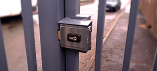
Similarly, pressing on the opening end of longer swing gates can damage gate motors and hardware. Long gate leaves (above 2.5m) should always be installed with a suitable electric lock. Magnetic ‘mag-locks’ will fail open if the power goes off. Electromechanical locks will remain secure if the power goes off and will normally have a key override to release them.
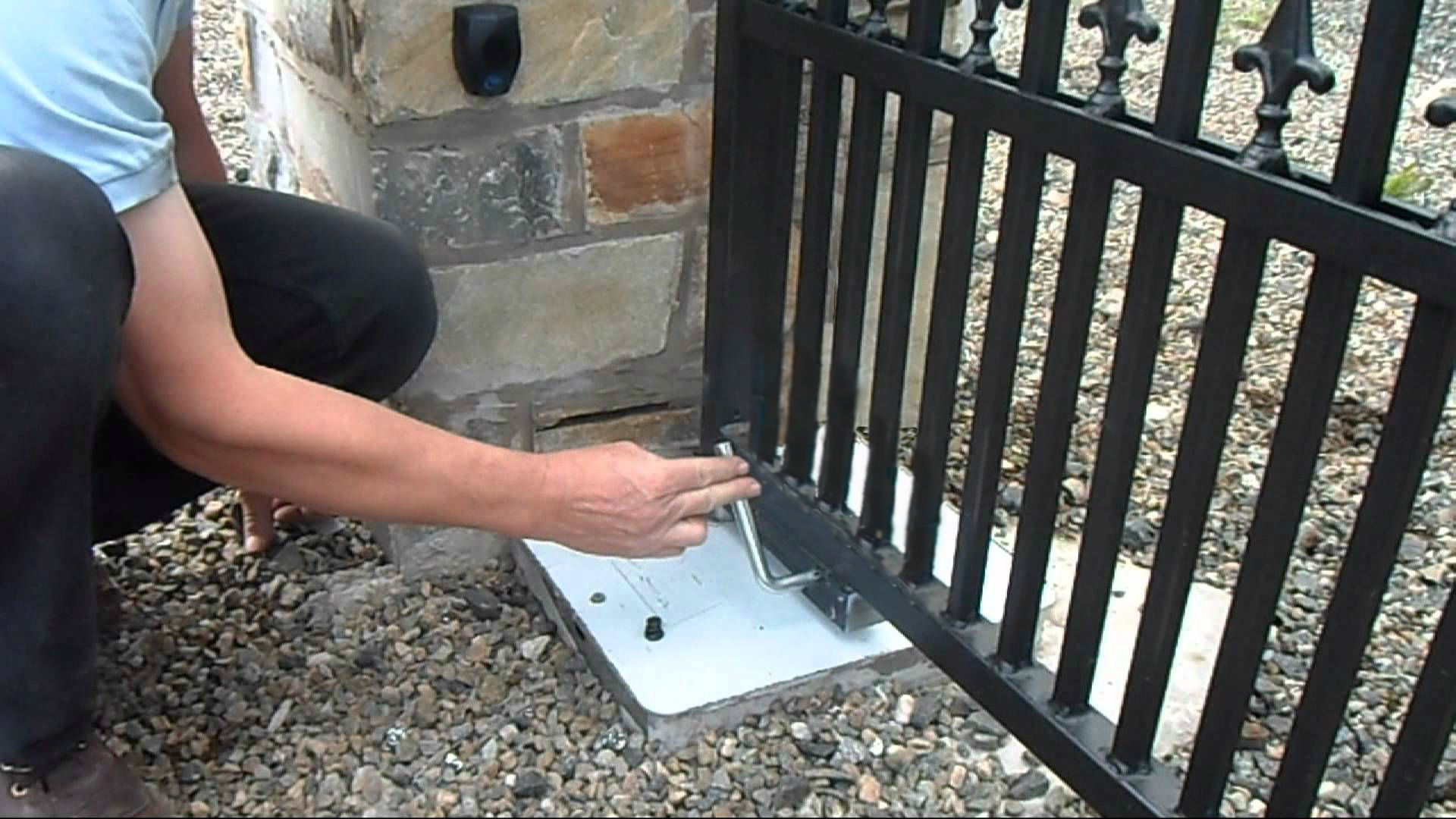
Manual release systems should always be added to any electric gate installation. The gate’s users should be trained to use the release and they should know where manual release keys are kept. If anyone does become trapped, quick use of a manual release disconnects the gates from the motors so the person can be freed. Manual releases should be tested regularly to ensure they are not seized when they are needed.
Before any gate automation system is designed, assembled and installed, a safety audit should be carried out. A good safety audit will identify how to:
1: Physically remove the risk types
2: Prevent access to the areas where the risk could exist
3: Teach the gate’s owners and any other users how to avoid the potential dangers.
There could still be many times when untrained users have to use the gates so methods 1 and 2 are always more effective because they remove the risk or stop access to a risk area.
Electronic safety devices can fail, and safety edges don’t work until the gate has hit something or someone. This means that physically removing risks and preventing access to risks that can’t be removed is the ultimate goal of safe automatic gate design.
The stages of a thorough risk assessment for a new or existing (where additional safety measure may be retrofitted) electric gate installation are as follows:
Step 1: The scope of the use of the gate, who will come into contact with it and what physical components, their location and the environment of the automatic gate are considered. This allows the parameters for the risk analysis to be established.
This stage should also consider the possible misuse of the gate by the untrained and those unaware of potential hazards created by the machinery.
Step 2: Once the parameters for the gate structure, location, components and operation have been considered, all the potential risks need to be understood and catalogued. This covers all stages of the gates’ life from installation and commissioning, operation, maintenance and disassembly.
Step 3: Once the potential risks that could exist within the parameters of the specific gate’s existence are understood, these risks should be prioritised based on how severe any injury they could cause might be and the likelihood of that risk occurring.
Once a hierarchy of risks has been established, the appropriate level of risk mitigation or elimination is determined. This is based on the following range of outcomes:
a: The risk is eliminated or reduced by the design of the gate automation system.
b: The risk is reduced by the application of safety devices added to the system.
c: Where it is not possible to incorporate a or b, warning signs and safety instruction are provided clearly for all users of the electric gates.
d: Measures for fast and safe release from the hazard are incorporated.
There is a set of British Standards that specifies the minimum requirements for a safe automatic electric gate.
These include:
BS EN 12453:2001 which recommends a minimum level of safeguarding against the crushing hazard at the closing edge of the gate depending on the type of environment in which the gate is operating. The Standard defines 3 types of use:
Type 1 - The gate is only used by trained users and there is no intended, inadvertent or unauthorised access to it by members of the public.
Type 2 - A limited group of persons (for example persons sharing a block of flats) are trained to operate the gate and the gate is located in a public area.
Type 3 - Any person is free to operate the gate and the gate is in contact with the general public.
The Standard advises on the minimum levels of safeguarding of the main gate edge according to its type of use. As Type 1 gates are controlled and operated by trained users, they are not covered in this safety notice because the gates are not located in the vicinity of the general public.
But Type 2 or Type 3 gates that have automatic control are accessible to untrained individuals including children and the elderly who may not understand the possible risks and put themselves into harm’s way with an unsafe gate. The Standard, therefore, gives advised level of safeguarding as follows:
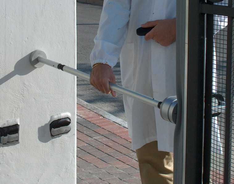
1) The forces that operate the gate leaves must be limited using force limitation devices or sensitive protective equipment
2) Provide ‘obstacle detection’ that recognises the presence of a person or an obstacle standing on the floor at one side of the gate.
The best solution is a means of detection that ensures that no-one can be touched by the moving gate leaf.
The Machinery Directive itself describes what needs to happen with regard to the assembly of components into a new machine and the paperwork and CE marking that is prepared by the installer creating the new machinery.
The list of Standards provided by the HSE includes:
BS EN 13241-1, Industrial, commercial and garage doors and gates. Harmonised product standard.
Supporting standards include:
1. BS EN 12453:2001, Industrial, commercial and garage doors and gates. Safety in use of power operated doors. Requirements.
2. BS EN 12445:2001, Industrial, commercial and garage doors and gates. Safety in use of power operated doors. Test methods.
3. BS EN 12978:2003, Industrial, commercial and garage doors and gates. Safety devices for power operated doors and gates.
Requirements and test methods.
4. BS EN 1760-2:2001, Safety of machinery. Pressure sensitive protective devices. General principles for the design and testing of pressure sensitive edges and pressure sensitive bars.
5. BS EN 12604:2000 Industrial, commercial and garage doors and gates. Mechanical aspects. Requirements.
6. BS EN 12605:2000 Industrial, commercial and garage doors and gates. Mechanical aspects. Test methods.
7. BS EN 12635:2002 Industrial, commercial and garage doors and gates. Installation and use (harmonised).
8. BS EN ISO 13857:2008 Safety of machinery. Safety distances to prevent hazard zones being reached by upper and lower limbs